




BLOGSDETAILS
Rotary Airlock Valve: Function and Application Guide
Author:hanzhe Time:2026-10-11 21:23:32 Click:166
A rotary airlock valve is one of the few components in a dust collection or bulk handling system that performs several jobs at once. It transfers material from one place to another, it separates two zones that sit at different pressures, and it meters the flow so the equipment downstream is neither starved nor flooded. When a system loses vacuum, dust escapes at the discharge, or a pneumatic line plugs repeatedly, the rotary airlock valve is frequently the first suspect for good reason.
This guide explains what the valve does, how its construction determines performance, which configurations exist, and what needs to be confirmed before a unit is bought. It is written for plant engineers, maintenance planners and procurement staff who have to justify the specification rather than just order a size.
What a Rotary Airlock Valve Does in a System
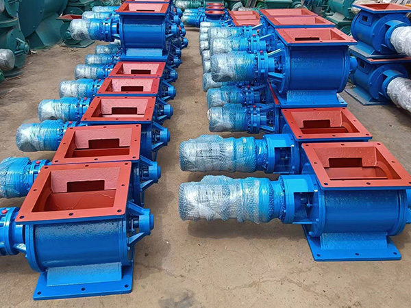
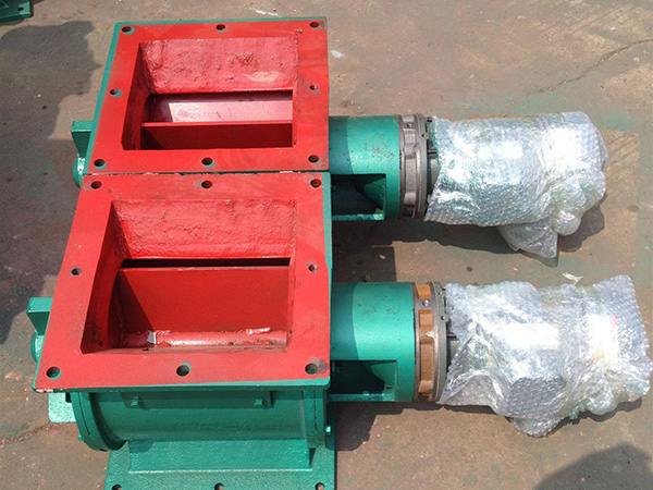
The valve is a rotating rotor with a fixed number of pockets, turning inside a close-fitting housing between an inlet flange and an outlet. Material drops into the pocket at the top, rotates with the rotor, and discharges at the bottom. Because the rotor tip passes close to the housing wall, the valve forms a moving seal between the inlet and outlet at all times.
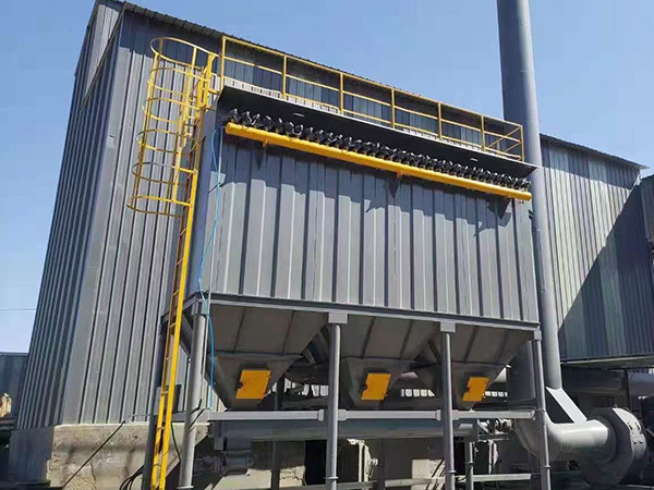
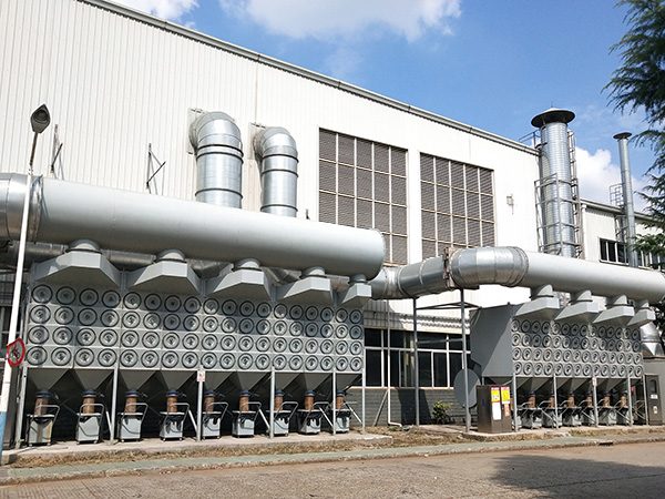
In a typical baghouse or cartridge dust collector, the valve sits under the hopper and discharges collected dust into a screw conveyor, a bin or a pneumatic conveying line. In pneumatic conveying, it feeds material into a pressurised line without letting the conveying air blow back into the hopper. In storage and bagging duty, it acts as a rotary discharge valve controlling the rate at which material leaves a silo. The same hardware, sized differently, serves all three duties.
Function One: Pressure Sealing
The sealing function is what the name describes. The valve maintains a pressure boundary between a low-pressure or atmospheric zone and a vacuum or pressurised zone. The quality of that seal depends on the clearance between the rotor tips and the housing, the number and geometry of the rotor pockets, and the condition of the discharge side.
Air leaking through the valve is not a cosmetic issue. In a dust collector, leakage raises the air-to-cloth ratio and can overload the fan; in pneumatic conveying, it reduces conveying velocity and can cause line blockage; in general dust handling, it can pull dust back out of the hopper and into the workplace. Because leakage is unavoidable, the practical target is to keep it within the design allowance, not to eliminate it.
Function Two: Metering and Discharge
A rotary valve also determines how much material leaves the system per unit of time. Volumetric throughput depends on the pocket volume swept per revolution and the rotor speed, modified by how well the pockets actually fill. Pockets that fill partially — because of poor inlet geometry, sticky material, or a rotor running too fast — reduce real capacity below the catalogue figure.
Matching the valve to the collector matters here. A hopper discharge valve that is too large dumps material in surges and can break the seal intermittently; one that is too small lets dust accumulate in the hopper, raising re-entrainment risk and loading the hopper structure. Valve throughput and collector dust generation rate should be compared at the design stage.
Function Three: Isolation and Safety
In systems handling combustible dust, the valve can act as an isolation device between the collector and downstream equipment, limiting the spread of a pressure wave. It can also serve as a maintenance isolation point so a conveyor or bin can be taken out of service without shutting down the collector. Whether a given valve qualifies as an isolation device depends on its construction, clearances and the applicable standards, so this should be confirmed with the supplier rather than assumed.
How the Valve Is Built
Rotor — typically six, eight or ten vanes. More vanes give more pockets and a steadier discharge but reduce the pocket volume for a given housing size.
Rotor tips — the wear surface in most applications. Replaceable or adjustable tips allow clearance to be re-established instead of replacing the entire rotor.
Housing — cast or fabricated, with inlet and outlet flanges. Surface finish and internal clearance control both leakage and wear.
Bearings and seals — normally mounted outside the material path. Outboard bearings reduce contamination, while the shaft seal prevents dust from reaching the bearing and prevents air from bypassing the rotor.
Drive — gear motor or chain drive, often with a torque limiter or shear pin to protect the rotor if a foreign object jams it.
Wear liners and coatings — applied to the housing and, where necessary, the tips when handling abrasive dust.
The rotary airlock valve range is built around this arrangement, and a simpler variant used purely for controlled discharge is described on the airlock feeder page.
Main Configurations
Configuration choices usually come down to how the material behaves and how the valve is installed.
Drop-through (gravity) valves — inlet at the top, outlet at the bottom, the standard arrangement under a collector hopper.
Blow-through valves — material is discharged directly into an air stream from the side, used where a pneumatic conveying line takes the material away.
Round or square flange options — selected to suit the hopper outlet and the connection to the downstream conveyor or bin.
Standard and reduced-clearance builds — tighter clearance reduces air leakage; more generous clearance tolerates thermal expansion and coarse or slightly irregular material.
Wear-resistant builds — hardened or lined housings and tips for fly ash, cement, foundry sand and mineral dust.
High-temperature builds — selected bearings, seals and clearances for hot dust, taking thermal expansion along the shaft into account.
Sanitary and corrosion-resistant builds — stainless construction and cleanable surfaces for food, pharmaceutical and chemical duty.
Selection Factors That Actually Decide Performance
Sizing a valve by flange size alone is the single most common specification error. The following points should be settled together.
Material — bulk density, particle size, abrasiveness, stickiness, moisture and temperature. A valve that works on cement dust may jam immediately on oily metal fines.
Required throughput — in mass per hour where possible, with the expectation that pockets will not fill completely.
Pressure differential — the vacuum or pressure the valve must seal against, since this drives rotor speed limits and clearance selection.
Temperature — hot dust requires expansion allowance and appropriate bearing and seal materials.
Clearance and leakage allowance — tighter is not automatically better. Excessively tight clearance in abrasive duty accelerates wear.
Drive protection — a torque limiter or shear pin is inexpensive protection against jamming by tramp material.
Orientation and access — the valve must be reachable for inspection and tip adjustment without dismantling ductwork.
Environment and duty cycle — continuous or intermittent operation, indoor or outdoor, and any applicable explosion-protection requirements.
Why Air Leakage Deserves Attention
Leakage through a rotary valve is normal, but unmanaged leakage is expensive. It appears as reduced fan performance, dust carry-over to the clean side of a collector, unstable pneumatic conveying, and higher energy consumption as the fan works harder to hold the set point. Free-flowing, very fine powders leak more readily because they offer less resistance as they pass the clearance.
Practical control measures include selecting clearance appropriate to the material rather than the tightest available, keeping the outlet sealed with an adequate discharge leg or conveyor, maintaining tip condition, and ensuring the valve speed matches the material's filling behaviour. In some processes a small air purge or vent arrangement at the valve is used to manage leakage, but this should be designed as part of the system rather than added later.
Common Failures and Maintenance Practice
Most valve problems fall into a short list. Rotor binding or jamming is usually caused by tramp metal, oversized material or product build-up between the tip and the housing. Excessive air leakage points to worn tips or an out-of-spec clearance. Bearing failure typically follows seal degradation, allowing dust into the bearing or losing lubrication. Tip and housing wear is expected in abrasive service and should be planned for as a consumable.
Maintenance is straightforward when the valve is accessible: check tip clearance on a fixed interval, verify seal condition, inspect the housing for grooving, confirm the drive protection device is intact and correctly rated, and confirm the discharge side is not blocked. A valve that is inspected at the same time as the collector's filter bags is far less likely to fail between outages. Related system-level detail is covered in the guide to baghouse dust collector design and operation.
Typical Applications
Baghouse and cartridge dust collector hopper discharge, usually feeding a screw conveyor or a storage bin.
Pneumatic conveying feed points, including dilute and dense phase systems.
Silo and bunker discharge where controlled, sealed extraction is required.
Foundry and metal finishing operations handling sand, shot and grinding dust.
Cement, lime, mineral processing and aggregate plants handling fine abrasive dust.
Food, feed and chemical plants where cleaning and corrosion resistance govern construction.
Ash handling and biomass plants, where hot or smouldering material may be present.
Information Needed for an Accurate Quotation
Suppliers who receive complete data can size a valve correctly the first time. The essential inputs are the material description with bulk density and temperature, the required discharge rate, the pressure or vacuum the valve must seal against, the flange size and orientation, the available power supply, and any wear, explosion-protection or hygiene requirements. Where the material is unknown or highly variable, saying so is more useful than providing an optimistic figure.
FAQ
What is the difference between a rotary airlock valve and a rotary feeder?
Both use the same rotor-in-housing principle, but the emphasis differs. An airlock valve is primarily selected for its sealing performance against a pressure differential. A rotary feeder is selected for consistent volumetric feed rate into a process or conveying line. Many units serve both functions, and the specification should state which duty dominates.
How much air leakage is normal for a rotary airlock valve?
Some leakage is inherent, because the rotor must turn with a clearance. Acceptable leakage depends on the differential pressure, rotor diameter, clearance and tip condition. Above the design allowance it shows up as fan overload, dust carry-over or unstable conveying, and should be investigated by checking tip wear and clearance rather than by simply adding vacuum.
Why does a rotary valve jam, and how can it be prevented?
Jamming is usually caused by foreign objects, oversized particles, sticky material bridging the inlet, or material packing between the rotor tip and housing. Prevention combines an inlet screen or magnet where appropriate, correct clearance for the material, a torque limiter or shear pin in the drive, and a discharge path that never backs up into the valve.
Can a rotary airlock valve be used with hot dust?
Yes, with a build specified for the temperature: high-temperature bearings and seals, appropriate clearances for thermal expansion, and often insulation or cooling considerations on the housing. The expected temperature and any short-term peaks should be stated in the enquiry, because a valve suited to ambient conditions may not survive a hot start-up or a process upset.
Should the valve run continuously or intermittently?
This depends on the collector's discharge pattern and the downstream equipment. Level-controlled intermittent running reduces wear and power consumption, while continuous running suits processes with steady dust generation. The drive and control arrangement, including any level sensor, is normally decided together with the collector or conveyor supplier.
References
Mills, D., Pneumatic Conveying Design Guide, 3rd ed., Butterworth-Heinemann, chapters on feeding devices and air leakage.
Klinzing, G.E., Rizk, F., Marcus, R. and Leung, L.S., Pneumatic Conveying of Solids: A Theoretical and Practical Approach, Springer.
U.S. Environmental Protection Agency, Air Pollution Control Technology Fact Sheet: Fabric Filter (Baghouses), EPA Air Pollution Control Technology Fact Sheet series.
National Fire Protection Association, NFPA 652: Standard on the Fundamentals of Combustible Dust, current edition.
European Parliament and Council, Directive 2014/34/EU on equipment and protective systems intended for use in potentially explosive atmospheres (ATEX).
Conclusion
A rotary airlock valve is a sealing device, a metering device and, in many installations, an isolation point. The engineering problem is that these three duties pull in different directions: tight clearances reduce leakage but increase wear and jamming risk, higher speed increases throughput but harms pocket filling, and the most economical construction is rarely the right one for abrasive or hot dust.
The selection factors that resolve this are material data, required discharge rate, pressure differential, temperature and duty cycle. Get them right and the valve becomes an unremarkable component that runs for years; get them wrong and it becomes a weekly maintenance item that drags the whole collector system down with it.
If you are specifying a valve for a new collector or replacing one that has not performed, send the material details, throughput, pressure and temperature conditions to our engineering team. We will recommend a configuration, flag any clearance or construction points that need confirming, and quote against the actual duty rather than a nominal flange size. Other system components, from knife gate valves to filter cages, are listed in the product centre.
 HOT PRODUCT
 CONTACT US