




BLOGSDETAILS
Pulse Jet Valve Working Principle in Dust Collection Systems
Author:hanzhe Time:2026-09-27 17:42:01 Click:164
The pulse jet valve is a small, low-cost component that does a disproportionate amount of work in any pulse-jet dust collector. Every few seconds, it fires a short burst of compressed air into a filter bag or cartridge, knocks the dust cake loose, and keeps the collector running. When a pulse jet valve fails, the corresponding filter loads up with dust, the pressure drop rises, the fan loses airflow, and the plant can quickly fall out of compliance. For buyers, maintenance leads, and engineers, understanding how a pulse jet valve works, what affects its performance, and how to specify the right one is fundamental to keeping a dust collection system healthy.
This guide covers the operating principle, the parts inside a typical valve, the role of pressure and timing, integration with the cleaning controller, common failure modes, and the practical factors that drive valve selection and replacement.
What Is a Pulse Jet Valve?
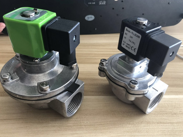
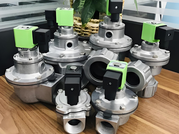
A pulse jet valve is a fast-acting, diaphragm-operated valve that releases a short, high-energy pulse of compressed air into a filter bag or cartridge. The pulse is initiated by an electrical signal to the solenoid coil, lasts for a few tens to a few hundreds of milliseconds, and dislodges the dust cake from the filter media by sending a shock wave down the bag.
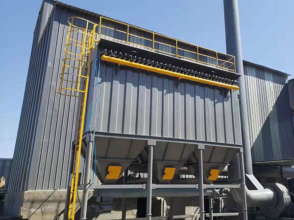
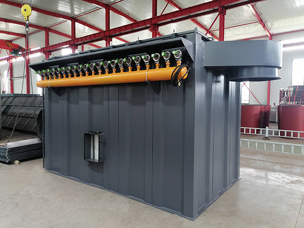
Pulse jet valves are the cleaning element at the heart of nearly every modern pulse-jet baghouse and every cartridge collector. They sit on a compressed-air manifold inside the clean-air plenum of the collector, with their outlet connected to a blow pipe or directly to a venturi above each filter row.
Working Principle of a Pulse Jet Valve
Although pulse valves look like simple on-off valves, the working principle is more subtle. There are three pressure zones that have to be balanced for the valve to open and close cleanly, and a small pilot valve that controls them.
Three Pressure Zones
Inlet (upstream) chamber: connected to the compressed-air supply. In a typical industrial dust collector, this is at 5–7 bar (80–100 psi).
Outlet (downstream) chamber: connected to the blow pipe and the filter. When the valve opens, this is where the cleaning pulse is delivered.
Top chamber above the main diaphragm: the small space on the dry side of the diaphragm. This is the control chamber that decides whether the valve is open or closed.
In the closed state, the pressure in the top chamber and the inlet are connected through a small bleed orifice, so the diaphragm is held down by the pressure differential. The main valve is closed.
When the solenoid is energized, a small pilot valve closes the bleed path. The air in the top chamber is exhausted through the pilot exhaust port faster than it can be replaced. The pressure in the top chamber drops, the diaphragm lifts, the main valve opens, and the full inlet pressure is delivered to the blow pipe and the filter as a cleaning pulse.
When the solenoid is de-energized, the bleed path reopens. Inlet pressure bleeds back into the top chamber, the pressure balance is restored, the diaphragm seats, and the main valve closes. The pulse ends.
Why the Diaphragm Design Matters
The diaphragm is the only moving wear part in most pulse valves. It has to flex millions of times over its life without fatigue, without losing seal, and without allowing the compressed air to leak past it during the closed state. The diaphragm material — typically a high-grade nitrile, fluoroelastomer (FKM/Viton), or silicone — and its geometry determine both the valve's response time and its service life.
Why the Pilot Valve Matters
The pilot valve controls the small volume of air that moves the diaphragm. If the pilot bleeds too slowly, the valve opens sluggishly and the cleaning pulse is weak. If the pilot bleeds too fast or leaks, the valve may stay open (a "stuck open" fault that wastes compressed air) or fail to close at all. The pilot is the most failure-sensitive part of the valve and is normally serviced as a kit together with the diaphragm.
Pulse Jet Valve Anatomy
Most industrial pulse jet valves for dust collection share the same general architecture.
Body: aluminum or stainless steel, threaded or flanged connection to the manifold and the blow pipe.
Main diaphragm: the principal moving element; sits between the inlet and the top chamber.
Pilot assembly: a small internal valve that bleeds air out of the top chamber when the solenoid is energized.
Solenoid coil: the electromagnetic element that drives the pilot; available in a range of voltages (24 V DC, 110 V AC, 220 V AC are common).
Diaphragm spring: a return spring that helps the diaphragm reseat when the pulse ends.
Seals and O-rings: static and dynamic seals, typically nitrile or FKM.
Manual override (on some models): a small knob or screw that allows the operator to fire the valve by hand for testing.
Role of Compressed Air Pressure and Reservoir
A pulse jet valve does not deliver a continuous flow of air; it delivers a short, high-energy pulse. To do that, the compressed-air supply must be able to deliver the volume of the pulse in a few tens of milliseconds. That places two requirements on the supply system.
Operating Pressure
Most industrial pulse valves are designed to operate at 5–7 bar (80–100 psi). Lower pressure reduces the cleaning force and leads to incomplete dust release, higher pressure drop, and shorter filter life. Higher pressure delivers more cleaning energy but accelerates diaphragm wear and consumes more compressed air. The right pressure depends on the filter type, the bag or cartridge length, the air-to-cloth ratio, and the dust characteristics — 6 bar (87 psi) is a common default.
Reservoir Volume
The compressed-air manifold that feeds the pulse valves acts as a reservoir. Its volume has to be large enough that firing one valve does not collapse the supply pressure for the next valve in the sequence. A common rule of thumb is to size the reservoir at about 50 times the volume of one pulse. If the manifold is undersized, the pulse loses energy and the cleaning is uneven across the filter bank.
Air Quality
Clean, dry air is essential. A refrigerated air dryer at the compressor outlet, a particulate filter, and a moisture separator on the manifold are a low-cost insurance policy. Dirty or wet air contaminates the diaphragm, the pilot, and the bleed orifice, and is the most common cause of premature valve failure.
Integration with the Cleaning Controller
The pulse jet valve is the actuator; the controller decides when it fires. There are three common control modes.
Time-Based Cleaning (On-Line)
The most common mode. The controller fires each valve in sequence at a fixed interval (for example, every 8 seconds, 6 valves in rotation, one row at a time). Time-based cleaning is simple, predictable, and easy to set up. The interval is chosen so that the pressure drop across the filters stays within a target range for the typical dust loading.
Differential Pressure (Delta-P) Cleaning
The controller monitors the pressure drop across the filters and fires a cleaning cycle only when pressure drop exceeds a set point. Delta-P cleaning saves compressed air on lightly loaded processes and is more responsive on processes with variable dust loading. Many modern controllers combine delta-P cleaning with a maximum time interval so that the filters are cleaned even if pressure drop stays low for too long.
Off-Line Cleaning
In some large baghouses, the filter bank is split into compartments and one compartment is taken offline for cleaning while the others continue filtering. Off-line cleaning is more efficient on heavily loaded processes but requires compartment isolation dampers and a more complex control system.
Common Failure Modes
Pulse jet valve failures usually show up in one of a few patterns. Recognizing the pattern makes the diagnosis straightforward.
Valve stays open (continuous leak): the most common failure. Compressed air flows continuously into the blow pipe, manifold pressure drops, the filters do not get cleaned on the next cycle, and the air compressor runs constantly to keep up. Cause: a torn diaphragm, a stuck pilot, a contaminated bleed orifice, or debris on the seat. Fix: rebuild the valve with a diaphragm and pilot kit, and check the compressed-air quality upstream.
Valve does not open: the corresponding filter loads up, pressure drop rises, and emissions increase. Cause: a failed solenoid coil, a broken wire, a clogged pilot, or no compressed air at the manifold. Fix: check the electrical signal at the coil, the air supply pressure, and the pilot assembly.
Weak pulse: cleaning is incomplete, pressure drop stays high, and the filters wear prematurely. Cause: low inlet pressure, undersized reservoir, partial diaphragm leak, or excessive leak elsewhere on the manifold. Fix: verify pressure, check the reservoir sizing, and rebuild suspect valves.
Slow or sticky operation: the valve opens and closes sluggishly, the cleaning cycle becomes irregular. Cause: contaminated pilot or bleed orifice, degraded diaphragm material, or air leaks at the seals. Fix: rebuild the valve, replace seals, and verify air quality.
Diaphragm rupture: the valve leaks continuously. Cause: end of diaphragm life, chemical attack, or freeze damage from moisture in the air supply. Fix: replace the diaphragm, identify the root cause, and add a dryer if moisture was the cause.
Selecting a Pulse Jet Valve
Pulse valves are commodity items in the sense that many manufacturers make equivalent products, but the wrong choice on body size, voltage, diaphragm material, or pressure rating will shorten life and increase maintenance. The factors below are the ones that matter.
Orifice Size and Flow Capacity
The valve orifice determines how much air flows per pulse. Standard sizes are typically 3/4 inch (20 mm), 1 inch (25 mm), 1.5 inch (40 mm), 2 inch (50 mm), and 2.5 inch (62 mm). The right size depends on the volume of air the pulse needs to deliver, which in turn depends on the bag or cartridge size and the cleaning intensity required. Undersizing the valve produces a weak pulse and poor cleaning; oversizing wastes compressed air and accelerates wear.
Pressure Rating
Standard valves are rated to 7–8 bar (100–120 psi). For plants with higher supply pressure, a higher-rated valve or a pressure regulator on the manifold is required.
Voltage and Electrical Connection
Common solenoid voltages are 24 V DC, 110 V AC, and 220 V AC. The right voltage depends on the controller. DIN connectors, conduit entries, and explosion-proof coil housings are available for different installation environments.
Diaphragm and Seal Material
Nitrile (NBR) is the default diaphragm material and works for most applications. FKM (Viton) is required for high-temperature or chemical exposure. Silicone and other specialty elastomers are available for unusual environments. The same material family should be used for the O-rings and the static seals to avoid material compatibility problems.
Body Material
Aluminum bodies are standard and economical. Stainless steel bodies are used in corrosive environments, food and pharmaceutical applications, and outdoor installations where corrosion is a concern.
Mounting and Manifold
Threaded and flanged connections are both common. Threaded connections are easier to install and replace in the field; flanged connections are preferred for larger valves and for high-cycle applications. The manifold itself should be sized to act as an adequate reservoir, and should be fitted with a pressure gauge, a safety relief valve, a manual drain, and a pressure regulator.
Pulse Jet Valve Maintenance
A small stock of spare valves and a regular inspection routine are the cheapest way to keep a pulse-jet collector healthy.
Inspect the manifold pressure daily; a steady drop in pressure often indicates a leaking valve.
Listen for the characteristic "click" of each valve as it fires. A change in sound (no click, weak click, continuous hiss) is the earliest sign of a problem.
Rebuild suspect valves with a diaphragm and pilot kit rather than replacing the whole valve, unless the body is damaged.
Keep a small stock of rebuild kits (typically 10–20% of installed valve count) so that a failed valve can be restored to service in minutes.
Replace solenoid coils on a planned interval rather than at failure, especially in continuous-duty applications.
Verify compressed-air quality at the manifold quarterly: a simple moisture test, a particulate check, and a pressure-decline test on a known leak-free system will catch most air-supply problems before they damage valves.
Troubleshooting Quick Reference
For the maintenance technician in the field, the table below is a quick way to convert a symptom into a likely cause.
Filter row with consistently high pressure drop: valve not firing — check electrical signal, solenoid coil, pilot, and air supply to that specific valve.
All filters showing high pressure drop: compressed-air supply problem — check compressor, dryer, manifold pressure, and look for a stuck-open valve leaking air.
Compressor running constantly: one or more stuck-open valves — listen at the manifold for continuous hiss, isolate valves one at a time to find the leak.
Short diaphragm life: chemical attack, moisture, or overpressure — verify diaphragm material compatibility, install a dryer if needed, and check the regulator setting.
Valve fires but cleaning is weak: low inlet pressure, undersized reservoir, or partial diaphragm leak — measure pressure at the manifold under load, check reservoir sizing, and rebuild the valve.
Frequently Asked Questions
What is the difference between a pulse jet valve and a solenoid valve?
A solenoid valve moves a small plunger to control a small flow of air; a pulse jet valve uses a solenoid-driven pilot to control the much larger flow through a diaphragm. The pilot is the only part the solenoid directly drives; the diaphragm does the heavy lifting. This is why pulse valves can deliver large cleaning pulses with a small, low-power solenoid.
What pressure does a pulse jet valve need?
Most industrial pulse valves are designed to operate at 5–7 bar (80–100 psi) of clean, dry compressed air. Lower pressure produces a weak cleaning pulse; higher pressure is wasteful and shortens diaphragm life.
How often does a pulse jet valve diaphragm need to be replaced?
On a stable process with clean air, a diaphragm typically lasts 1–2 years of continuous duty. On processes with oily or chemically aggressive air, life can be much shorter. A preventive replacement schedule based on operating hours is more reliable than waiting for failure.
Can pulse jet valves from different manufacturers be mixed on the same manifold?
Mechanically, in many cases yes — many manufacturers follow the same body dimensions and connection standards. Electrically, the solenoid voltage and connector must match the controller. Pneumatically, the valves should be similar in flow capacity so the cleaning is even. Mixing brands is acceptable when the specifications are matched, but it is best to standardize on one supplier for spare parts simplicity.
How do I know if a pulse jet valve is the cause of high pressure drop?
Open the clean-air plenum and listen at each valve while the cleaning cycle runs. A normal valve produces a sharp "click" and a brief hiss as the pulse fires. A failed valve is silent (not firing) or hissing continuously (stuck open). A valve that clicks but does not deliver a strong pulse may have a partial diaphragm leak; isolating the suspect valve and rebuilding it with a kit is the standard field test.
Conclusion
The pulse jet valve is a small component that has an outsized effect on the reliability and emission performance of any pulse-jet dust collector. Understanding the three pressure zones, the role of the diaphragm and the pilot, the requirement for clean dry air, and the integration with the cleaning controller turns valve maintenance from a reactive chore into a planned, low-cost activity. For buyers and engineers, specifying the right valve — correct orifice size, correct voltage, correct diaphragm material, correct body material — and keeping a small stock of rebuild kits is the most cost-effective way to keep a dust collection system running for the long term.
To discuss a specific valve, a cleaning system upgrade, or a complete baghouse retrofit, contact the engineering team through the contact page or revisit themain product overview to see the full range of dust collection equipment, replacement parts, and consumables.
References
U.S. Environmental Protection Agency. AP-42: Compilation of Air Emissions Factors from Stationary Sources.
Compressed Air and Gas Institute. Compressed Air and Gas Handbook (7th ed.).
National Fire Protection Association. NFPA 654: Standard for the Prevention of Fire and Dust Explosions from the Manufacturing, Processing, and Handling of Combustible Particulate Solids.
Occupational Safety and Health Administration. Mechanical Power-Transmission Apparatus (29 CFR 1910.219).
Cooper, C. D., & Alley, F. C. (2011). Air Pollution Control: A Design Approach (4th ed.). Waveland Press.
 HOT PRODUCT
 CONTACT US