




BLOGSDETAILS
Complete Components of an Industrial Dust Collector System
Author:hanzhe Time:2026-10-20 22:16:15 Click:86
A dust collector is rarely a single box. It is one stage in a chain that begins at the machine generating the dust and ends at a hopper or bin. Treating the filter housing as the whole "system" is the most common reason installations underperform: the collector can be perfectly sized and still fail if the capture, ductwork, fan or discharge equipment is wrong. This guide breaks the system into its functional components and explains how they fit together.
Capture: Hoods, Enclosures and Pickup Points
Everything starts at capture. A hood, enclosure or extractor collects the contaminated air at the source before it disperses into the workspace. The design goal is to capture the dust with the lowest airflow that still contains it, because every cubic metre per hour added here raises the size and cost of every downstream component. Capture effectiveness is a function of hood type, enclosure, distance from the source and local air currents, not of the collector.
Ductwork and Airflow Distribution
The duct network carries the captured air to the collector. Duct velocity must be high enough to keep dust suspended and prevent drop-out, but not so high that energy and abrasion increase unnecessarily. Branch sizing, smooth transitions and correct main sizing keep the pressure drop predictable. Ductwork also determines the system's total static resistance, which the fan must overcome, so duct changes during a retrofit ripple through the whole balance.
Filter Housing
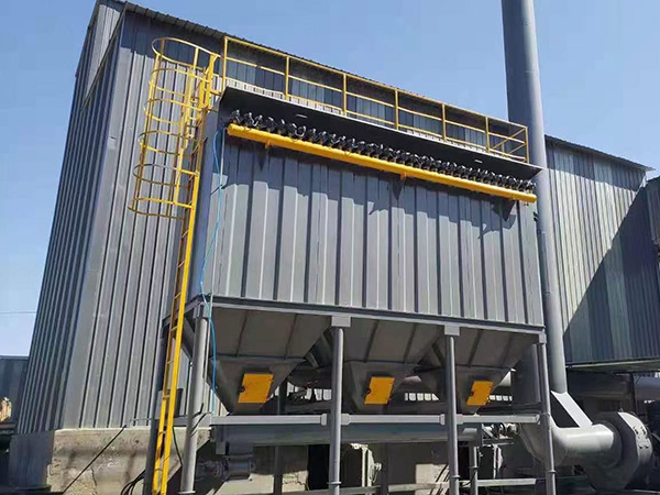
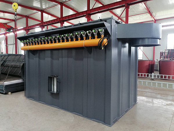
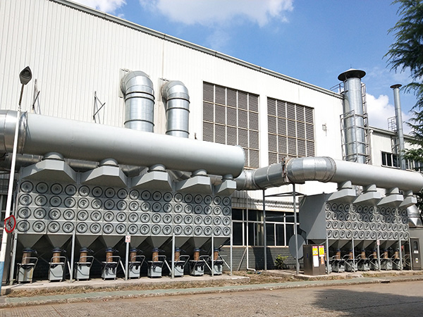
The housing contains the filtration stage. The two mainstream forms are baghouse and cartridge collectors. A baghouse uses cylindrical filter bags in a larger housing and suits high dust loadings and heavier continuous duty; a baghouse dust collector and its pulse-jet variant are described in the product range. A cartridge collector packs pleated media into a smaller footprint and suits dry, fine, free-flowing dust from metalworking and cutting. The choice between them follows the dust, covered in more depth in the guide to selecting industrial air filtration equipment.
Filter Media and Cages
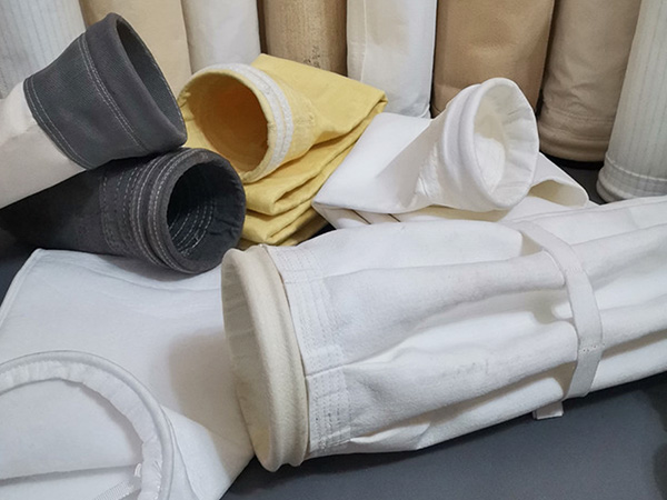
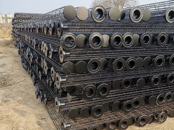
The media does the actual capturing, and the filter bag must be matched to the cleaning intensity, temperature and dust chemistry. Inside a baghouse, a filter bag cage supports the bag against the cleaning pulse and prevents collapse. Media selection and sizing decide both emission performance and how often bags are replaced, which is why the consumable is better evaluated on life cost than on unit price.
Cleaning System
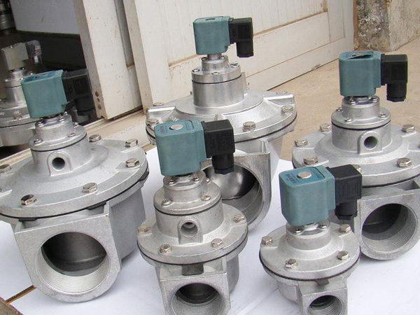
In pulse jet collectors, the cleaning system regenerates the media on-line using short bursts of compressed air. It comprises the air reservoir, the pulse jet valve, blowpipes and nozzles, and the controller. The cleaning logic — how often and under what trigger the pulses fire — strongly affects energy use and media life, and is discussed separately in the article on pulse cleaning and efficiency.
Air Mover: Fan and Motor
The fan creates the airflow that pulls contaminated air in and pushes cleaned air out. It is usually the largest energy consumer in the system. Fan selection depends on the total required airflow and the total system static resistance, including the loaded filter, the ductwork and any discharge equipment. An oversized fan wastes energy and can disturb the pressure balance at the hopper; an undersized fan cannot hold capture velocity. Variable frequency drives allow the fan to track the actual demand rather than running flat-out.
Discharge and Material Handling
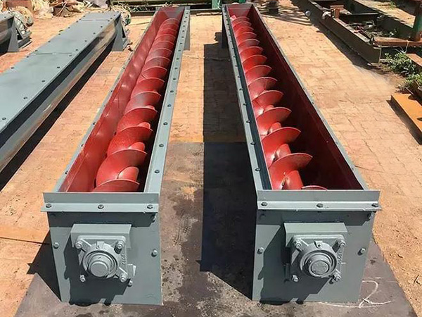
Collected dust has to leave the hopper continuously or in batches. A rotary airlock valve maintains the pressure seal under the hopper while discharging dust, and a screw conveyor transfers it away from the collector to a bin, silo or process. If discharge is ignored, dust builds in the hopper, raises re-entrainment and can overload the structure. For compact point-source dust, a grinding downdraft table integrates capture and filtration so there is no separate duct run to design.
Controls and Instrumentation
The control system coordinates cleaning, fan operation and alarms. At minimum, a differential-pressure indicator shows whether the media and cleaning are healthy — it is the single most useful operating signal. Timers or differential-pressure-based controllers manage the cleaning sequence, and interlocks protect against operating the fan with the discharge blocked or the cleaning air lost. More advanced systems add VFD fan control, hopper level indication and remote monitoring.
Safety and Compliance Elements
Depending on the dust and jurisdiction, the system may include explosion vents, rotary or chemical isolation devices, spark arrestors upstream, and conductive ducting and grounding. These elements interact: a vent is only effective if connected equipment is isolated, and the discharge valve must not become an ignition source. Requirements vary, so they should be designed in from the start rather than added later.
How the Components Interact
The point of listing the components is to show that they are coupled. A misaligned hood raises required airflow, which raises fan energy and forces more frequent cleaning, which shortens media life. A blocked discharge raises the hopper level and re-entrains dust, which looks like a media problem but is not. A duct redesign changes the pressure drop and can move the fan off its best efficiency point. For this reason, the most reliable route to a good system is to design it as one, with the capture, filtration, fan and discharge specified together against the same operating data.
FAQ
What are the main parts of a dust collection system?
The functional parts are capture points, ductwork, the filter housing with media and cages, the cleaning system, the fan and motor, the discharge and material-handling equipment, controls and instrumentation, and any required safety or compliance elements. Each is sized against the same airflow and dust data.
Can I add a dust collector to an existing process without changing the ductwork?
Sometimes, but the ductwork sets the airflow and resistance that the collector and fan must match. Tying a new collector into existing ducts usually changes the balance across the whole system, so a fresh airflow and pressure-drop assessment is advisable before sizing the fan.
Why is the discharge equipment considered part of the system?
Because collected dust has to leave continuously. If the hopper discharge, airlock or conveyor cannot keep up, dust accumulates, re-entrains into the cleaned gas and loads the media again, which presents as a filter problem but originates at discharge.
Which component uses the most energy?
Typically the fan, because it runs continuously against the full system resistance. Cleaning compressed air is the next significant consumer, and both are reduced by correct capture design, proper sizing and demand-based cleaning rather than by changes to the filter media alone.
Do all dust collector systems need explosion protection?
Only those handling combustible dust, and the specific measures depend on the material, concentration and system layout, as well as local requirements. The correct approach is a dust hazard assessment that determines whether vents, isolation and conductive construction are needed, not a standard package applied to every installation.
References
ACGIH, Industrial Ventilation: A Manual of Recommended Practice for Design, current edition.
U.S. Environmental Protection Agency, Air Pollution Control Technology Fact Sheets, including the fabric filter fact sheet.
National Fire Protection Association, NFPA 652: Standard on the Fundamentals of Combustible Dust, current edition.
National Fire Protection Association, NFPA 654: Standard for the Prevention of Fire and Dust Explosions, current edition.
Cooper, C.D. and Alley, F.C., Air Pollution Control: A Design Approach, Waveland Press.
Conclusion
The technical problem in building a dust collector system is that the filter housing is only one component in a coupled chain. Capture design sets the airflow that every downstream part must handle; ductwork sets the resistance the fan must overcome; the cleaning system sets the media life and energy use; and the discharge equipment decides whether collected dust leaves the system or returns to it.
The considerations that determine success are airflow at the source, total system resistance, filtration area sized to the dust, a cleaning strategy matched to the load, a fan sized to the real operating point, and discharge that keeps up. The practical value of treating these as one system is lower energy, longer media life and fewer failures that masquerade as filter problems.
If you are specifying or upgrading a system, send the process and dust data, capture points and any existing duct information. Our engineering team at Hanzhe Environmental Protection will review the component balance and flag the points that need confirming. The full equipment range is in the product centre, and installed examples are shown in the case studies.
 HOT PRODUCT
 CONTACT US